 EN

Vacuum Conveying System Design Basics for Pharmaceutical Plants
A vacuum transfer system can connect powder handling steps without relying on open manual transfer. In a pharmaceutical plant, however, the first design question is not simply how much powder must move per hour. The useful question is whether the complete material path—from bag discharge or charging point to receiver and downstream equipment—can support containment, cleanability, batch changeover, and stable operation.
From a solid-dosage equipment selection perspective, the vacuum transfer system should first be matched to material behavior and the process node it serves. A design that moves a free-flowing excipient well may need different air handling, receiver geometry, filter cleaning, and discharge control for cohesive blends or dust-sensitive actives. This article outlines the design basics a process, production, quality, and procurement team can review together.
Start With the Pharmaceutical Material Path
A vacuum transfer system creates negative pressure at the receiving end and draws material through enclosed pipework. That basic arrangement is valuable where an enclosed route can reduce open handling, but the layout must still reflect the real production sequence. Map every point where material enters, changes direction, pauses, discharges, or is exposed during inspection.
- Feed point: Identify the container, charging station, sack tip, IBC, or hopper that supplies the material.
- Conveying route: Define pipe length, vertical lifts, bends, flexible connections, and points that need dismantling or inspection.
- Receiver: Confirm how the receiver separates air from product and how it discharges into the next machine.
- Downstream interface: Check the flange, height, buffer capacity, and control logic at the blender, mill, sieve, tablet press, or other receiving equipment.
It is usually easier to validate a layout when the material path is drawn before a supplier is asked to size the system. In other words, do not select a vacuum transfer system from throughput alone. First confirm powder flowability, bulk density, particle-size distribution, moisture sensitivity, dust behavior, required batch size, and the allowable hold-up in the route.
Define the Duty Cycle, Not Only the Hourly Capacity
Pharmaceutical transfer is often batch-based. A line may need short, repeatable conveying cycles followed by discharge, blending, sampling, or downstream processing. That means the duty cycle matters as much as an hourly number. A practical duty definition states the mass per cycle, number of cycles, transfer distance, receiving vessel level, and the time available between cycles.
Ask how the vacuum transfer system behaves when the receiver is full, when a filter needs cleaning, or when the downstream machine pauses. These operating states determine whether the system needs level sensing, interlocks, a buffer hopper, or changes to the feeding method. If material characteristics and the target process rate are already clear, this evaluation is much easier to verify; if they are not, treat the figures as items for trial and technical clarification rather than fixed promises.
Build Hygienic Design Into the Layout
For pharmaceutical manufacturing, a vacuum transfer system should be reviewed as a cleanable process assembly rather than as a pump and pipe set. In the United States, 21 CFR Part 211 states that equipment should be appropriately designed, sized, and located to facilitate its intended use, cleaning, and maintenance. It also requires suitable product-contact surfaces and written cleaning and maintenance procedures. The applicable regulatory framework and site quality system should be confirmed by the plant.
Translate those principles into equipment questions: Can product-contact parts be accessed? Are seals, filters, gaskets, and flexible hoses included in the cleaning plan? Does the pipe route avoid unnecessary dead legs or difficult-to-reach areas? Can the receiver be opened and reassembled consistently? More accurately, the key issue is not whether one component looks hygienic in isolation, but whether the entire material path can be cleaned, inspected, protected after cleaning, and documented within the site procedure.
For multi-product facilities, changeover planning deserves early attention. Consider whether dedicated contact parts, removable sections, wash-in-place provisions, or validated manual cleaning steps are appropriate for the product and risk assessment. The answer depends on the formulation, containment needs, cleaning validation strategy, and local operating practice.
Coordinate Air, Filtration, and Containment
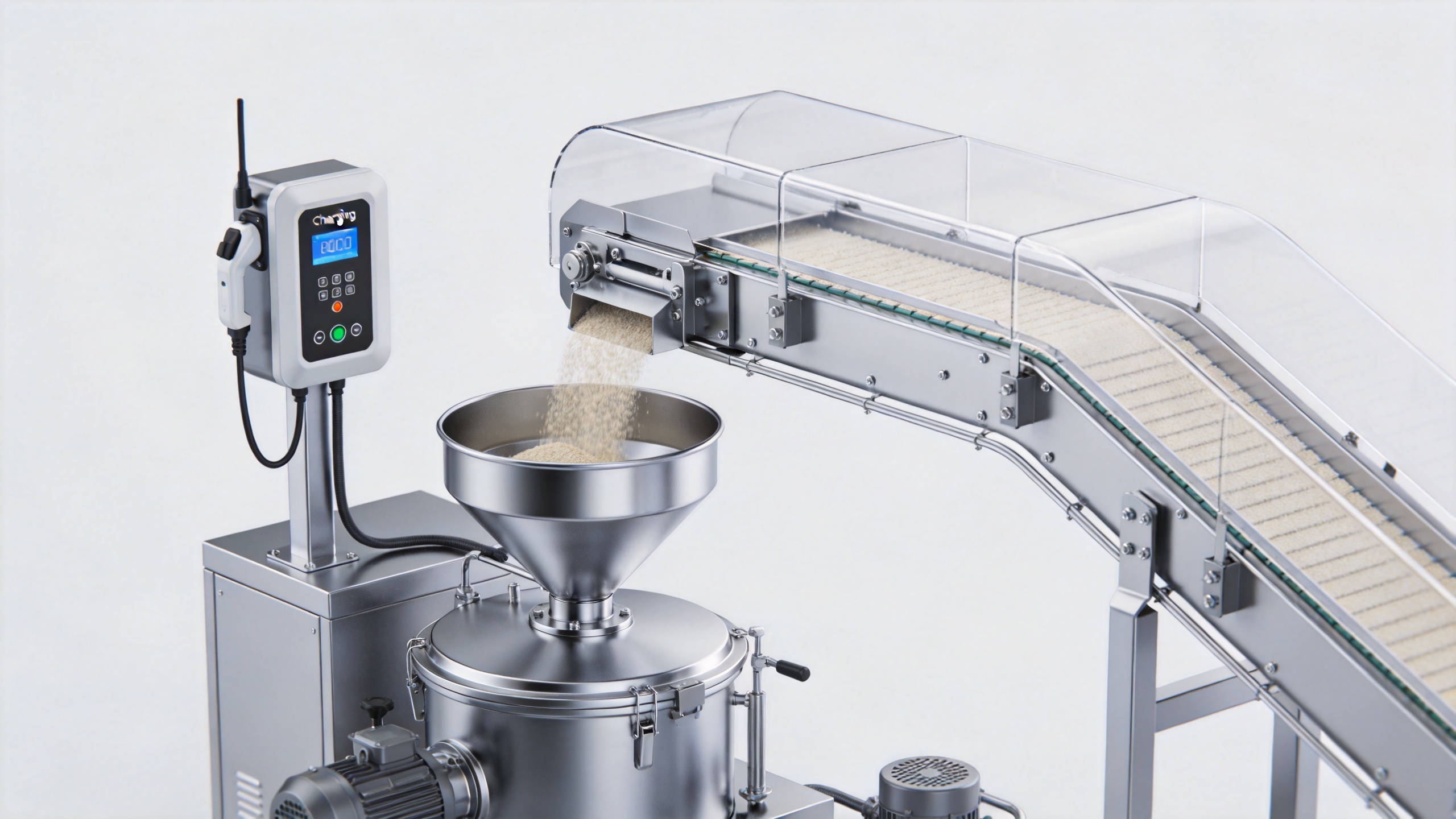
Every vacuum transfer system moves air as well as product. The receiver filter must separate the transport air from powder while allowing the chosen conveying cycle to continue. Filter area, media, cleaning method, and differential-pressure monitoring are therefore process decisions, not afterthoughts. A poorly coordinated filter arrangement can interrupt transfer, increase cleaning work, or create unstable operating behavior.
Containment also requires a whole-system view. Review the feed point, receiver venting, filter change method, discharge interface, and any maintenance access together. Where hazardous or potent materials are involved, the final design should be set through the plant’s formal containment assessment and applicable safety requirements. A general blog article cannot replace that assessment.
Make Equipment Interfaces Explicit
Vacuum conveying is most reliable when interfaces are specified rather than assumed. Record the receiving machine inlet size, available headroom, vessel pressure conditions, control signals, and the cleaning ownership for each connection. If the transfer system feeds more than one destination, define how routing, isolation, and cleaning status will be controlled.
For an example of a product category used in this type of material-handling discussion, see the ELECTRIC VACUUM FEEDER ZKS. The final suitability of any equipment configuration still depends on the verified material data, process layout, and site requirements; a product name alone does not establish a complete pharmaceutical design.
How to Size the Vacuum Transfer System Inputs
To make a vacuum transfer system proposal technically meaningful, give the engineering team a defined set of inputs rather than a single capacity target. The minimum information normally includes the material bulk density, particle-size range, flow behavior, moisture sensitivity, batch mass, transfer distance, elevation change, and the required receiving point. The team should also identify whether the material is a single ingredient, a preblend, or a blend whose segregation risk needs to be evaluated.
Pipe diameter and route geometry are then selected as part of the vacuum transfer system design, together with the air source, receiver volume, filtration arrangement, and discharge valve. Shorter, more direct routes are often simpler to inspect and clean, but the final route must work with the building layout and maintenance access. Avoid treating one preliminary sizing calculation as a fixed production result: a material trial or approved design review is the appropriate way to confirm the operating window.
During this review, list the conditions that could alter performance. Examples include changes in supplier particle distribution, humidity, formulation composition, container presentation, or downstream demand. This creates a clearer basis for acceptance testing and for later change control. A vacuum transfer system that has defined operating limits is generally easier for production teams to operate consistently than one sized only around a nominal maximum rate.
Plan Cleaning and Changeover as Operating Tasks
Cleaning should be considered while the vacuum transfer system is still a layout drawing. Identify each product-contact component, the access point used to inspect it, the cleaning method, the tools required, and the condition that shows the unit is ready to return to service. Include receiver interiors, filter housings, discharge valves, gaskets, pipe sections, flexible connections, and any feed adapters in the discussion.
For manual cleaning, the practical test is whether personnel can dismantle, clean, inspect, reassemble, and protect the parts without creating avoidable ambiguity. For automated cleaning, define the validation approach, drainage behavior, utility connections, and recovery steps with the site team. These choices should align with the plant’s written procedures and quality requirements. They should not be inferred solely from a catalogue image or a generic equipment description.
A Practical Design Review Checklist
- Document the material characteristics, batch quantity, target transfer rate, and process sequence.
- Sketch the full route, including feed source, pipe runs, receiver, discharge point, and maintenance access.
- Set the duty cycle and identify downstream pause conditions and level-control requirements.
- Review product-contact materials, seals, filters, dismantling points, and cleaning responsibilities with quality and production.
- Assess containment, dust control, and filter servicing through the formal site risk process.
- Confirm controls, interlocks, utilities, and factory/site acceptance criteria before procurement.
A well-scoped vacuum transfer system design does more than move powder. It makes the material path understandable, keeps cleaning and maintenance considerations visible, and gives cross-functional teams clear conditions to verify before installation. Start with the material and the production route, then use trials and technical clarification to finalize the equipment details.